


Special Offer
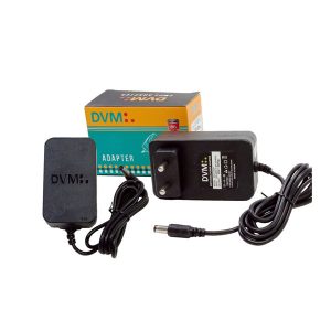
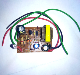
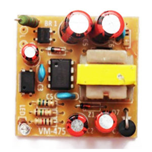
15V 2Amp Adapter SMPS Power AC 100-240 V Premium
₹354.00-
Modules & Sensors
HX711 Weighing Sensor Dual-Channel 24 Bit Precision A/D Module Pressure Sensor
Features:
- Two selectable differential input channels
- On-chip active low noise PGA with selectable gain of 32, 64 and 128
- On-chip power supply regulator for load-cell and ADC analog power supply
- On-chip oscillator requiring no external component with optional external crystal
- On-chip power-on-reset
- Simple digital control and serial interface: pin-driven controls, no programming needed
- Selectable 10SPS or 80SPS output data rate
- Simultaneous 50 and 60Hz supply rejection
- Current consumption including on-chip analog power supply regulator: normal operation < 1.5mA, power down <1uA
- Operation supply voltage range: 2.6 ~ 5.5V
- Size:40mmx20mm/1.56″x0.79″(inch) (approx)
- Weight 3 Grams
SKU: CE-M068 -
Components, Transistors
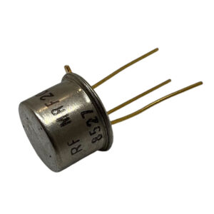
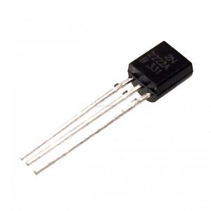
2N3866A NPN RF Power Transistor – Metal Package
QUICK OVERVIEW
- RF & MICROWAVE DISCRETE LOW POWER TRANSISTORS
- Silicon NPN, To-39 packaged VHF/UHF Transistor
- Specified 400 MHz, 28Vdc Characteristics
– Output Power = 1.0 Watt
– Minimum Gain = 10 dB
– Efficiency = 45% - 800 MHz Current-Gain Bandwidth Product
For Download Datasheet Please click bellow link
https://datasheetspdf.com/pdf-file/1114831/Motorola/2N3866A/1
SKU: CE-MT700 -
Components
SN74HC595N, 8-Bit Shift Register ICs
Features:
- 8-bit
- Logic Family : HC
- Logical Function : Shift Register
- Operating Supply Voltage (Typ) : 5V
- Output Type : 3-State
- Package Type : DIP
- Propagation Delay Time : 265ns
- Operating Temp Range : -40C to 125C
- Operating Supply Voltage (Min) : 2V
- Operating Supply Voltage (Max) : 6V
You Will Get :
- SN74HC595N IC = 1
- 16 Pin IC Base = 1
SKU: CE-IC004 -
Developments Boards
Arduino UNO R3 Atmega16U2 With Cable
The Arduino Uno R3 is a micro-controller board base on the ATmega328. It has 14 digital input/output pins (of which 6 can be used as PWM outputs); 6 analog inputs, a 16 MHz ceramic resonator, a USB connection, a power jack, an ICSP header, and a reset button. It contains everything need to support the micro-controller; simply connect it to a computer with a USB cable or power it with a AC-to-DC adapter or battery to get start.
The Arduino Uno R3 differs from all preceding boards in that it does not use the FTDI USB-to-serial driver chip. Instead, it features the Atmega16U2 (Atmega8U2 up to version R2) program as a USB-to-serial converter. Revision 2 of the Uno board has a resistor pulling the 8U2 HWB line to ground, making it easier to put into DFU mode.
“Uno” means one in Italian and is name to mark the upcoming release of Arduino 1.0. The Uno and version 1.0 will be the reference versions of Arduino, moving forward. The Uno is the latest in a series of USB Arduino boards, and the reference model for the Arduino platform; for a comparison with previous versions, see the index of Arduino boards.
Note: The Arduino Uno R3 reference design can use an Atmega8, 168, or 328, Current models use an ATmega328, but an Atmega8 is shown in the schematic for reference. The pin configuration is identical on all three processors.
Power :
The Arduino Uno R3 can be powered via the USB connection or with an external power supply. The power source is selected automatically.
External (non-USB) power can come either from an AC-to-DC adapter (wall-wart) or battery. The adapter can be connected by plugging a 2.1mm center-positive plug into the board’s power jack. Leads from a battery can be inserted in the Gnd and Vin pin headers of the POWER connector.
The board can operate on an external supply of 6 to 20 volts. If supplied with less than 7V, however, the 5V pin may supply less than five volts and the board may be unstable. If using more than 12V, the voltage regulator may overheat and damage the board. The recommended range is 7 to 12 volts.
The power pins are as follows :
- VIN. The input voltage to the Arduino board when it’s using an external power source (as opposed to 5 volts from the USB connection or other regulated power source). You can supply voltage through this pin, or, if supplying voltage via the power jack, access it through this pin.
- 5V.This pin outputs a regulated 5V from the regulator on the board. The board can be supplied with power either from the DC power jack (7 – 12V), the USB connector (5V), or the VIN pin of the board (7-12V). Supplying voltage via the 5V or 3.3V pins bypasses the regulator, and can damage your board. We don’t advise it.
- 3V3. A 3.3 volt supply generated by the on-board regulator. Maximum current draw is 50 mA.
- GND. Ground pins.
- IOREF. This pin on the Arduino board provides the voltage reference with which the microcontroller operates. A properly configured shield can read the IOREF pin voltage and select the appropriate power source or enable voltage translators on the outputs for working with the 5V or 3.3V.
Memory :
The ATmega328 has 32 KB (with 0.5 KB used for the bootloader). It also has 2 KB of SRAM and 1 KB of EEPROM (which can be read and written with the EEPROM library).
Input and Output :
Each of the 14 digital pins on the Uno can be used as an input or output, using pinMode(), digitalWrite(), anddigitalRead() functions. They operate at 5 volts. Each pin can provide or receive a maximum of 40 mA and has an internal pull-up resistor (disconnected by default) of 20-50 kOhms. In addition, some pins have specialized functions:
- Serial: 0 (RX) and 1 (TX). Used to receive (RX) and transmit (TX) TTL serial data. These pins are connected to the corresponding pins of the ATmega8U2 USB-to-TTL Serial chip.
- External Interrupts: 2 and 3. These pins can be configured to trigger an interrupt on a low value, a rising or falling edge, or a change in value. See the attachInterrupt() function for details.
- PWM: 3, 5, 6, 9, 10, and 11. Provide 8-bit PWM output with the analogWrite() function.
- SPI: 10 (SS), 11 (MOSI), 12 (MISO), 13 (SCK). These pins support SPI communication using the SPI library.
- LED: 13. There is a built-in LED connected to digital pin 13. When the pin is HIGH value, the LED is on, when the pin is LOW, it’s off.
The Arduino Uno R3 has 6 analog inputs, labeled A0 through A5, each of which provide 10 bits of resolution (i.e. 1024 different values). By default they measure from ground to 5 volts, though is it possible to change the upper end of their range using the AREF pin and the analogReference() function. Additionally, some pins have specialized functionality:
- TWI: A4 or SDA pin and A5 or SCL pin. Support TWI communication using the Wire library.
There are a couple of other pins on the board:
- AREF. Reference voltage for the analog inputs. Used with analogReference().
- Reset. Bring this line LOW to reset the microcontroller. Typically used to add a reset button to shields which block the one on the board.
See also the mapping between Arduino pins and ATmega328 ports. The mapping for the Atmega8, 168, and 328 is identical.
Communication :
The Arduino Uno R3 has a number of facilities for communicating with a computer, another Arduino, or other microcontrollers. The ATmega328 provides UART TTL (5V) serial communication, which is available on digital pins 0 (RX) and 1 (TX). An ATmega16U2 on the board channels this serial communication over USB and appears as a virtual com port to software on the computer. The ’16U2 firmware uses the standard USB COM drivers, and no external driver is needed. However, on Windows, a .inf file is required. The Arduino software includes a serial monitor which allows simple textual data to be sent to and from the Arduino board. The RX and TX LEDs on the board will flash when data is being transmitted via the USB-to-serial chip and USB connection to the computer (but not for serial communication on pins 0 and 1).
A SoftwareSerial library allows for serial communication on any of the Uno’s digital pins.
The ATmega328 also supports I2C (TWI) and SPI communication. The Arduino Uno R3 software includes a Wire library to simplify use of the I2C bus; see the documentation for details. For SPI communication, use the SPI library.
Programming :
The Arduino Uno R3 can be program with the Arduino software (download). Select “Arduino Uno from the Tools > Board menu (according to the micro-controller on your board). For details, see the reference and tutorials.
The ATmega328 on the Arduino Uno R3 comes pre burn with a bootloader that allows you to upload new code to it without the use of an external hardware programmer. It communicates using the original STK500 protocol (reference, C header files).
You can also bypass the bootloader and program the microcontroller through the ICSP (In-Circuit Serial Programming) header; see these instructions for details.
The ATmega16U2 (or 8U2 in the rev1 and rev2 boards) firmware source code is available . The ATmega16U2/8U2 is load with a DFU bootloader, which can be activate by:
- On Rev1 boards: connecting the solder jumper on the back of the board (near the map of Italy) and then resetting the 8U2.
- On Rev2 or later boards: there is a resistor that pulling the 8U2/16U2 HWB line to ground, making it easier to put into DFU mode.
You can then use Atmel’s FLIP software (Windows) or the DFU programmer (Mac OS X and Linux) to load a new firmware. Or you can use the ISP header with an external programmer (overwriting the DFU bootloader). See this user-contributed tutorial for more information.
Automatic (Software) Reset :
Rather than requiring a physical press of the reset button before an upload, the Arduino Uno is design in a way that allows it to be reset by software running on a connect computer. One of the hardware flow control lines (DTR) of theATmega8U2/16U2 is connected to the reset line of the ATmega328 via a 100 nano-farad capacitor. When this line is assert (taken low), the reset line drops long enough to reset the chip. The Arduino software uses this capability to allow you to upload code by simply pressing the upload button in the Arduino environment. This means that the boot-loader can have a shorter timeout, as the lowering of DTR can be well-coordinate with the start of the upload.
This setup has other implications. When the Uno is connect to either a computer running Mac OS X or Linux, it resets each time a connection is made to it from software (via USB). For the following half-second or so, the boot-loader is running on the Uno. While it is program to ignore malformed data (i.e. anything besides an upload of new code), it will intercept the first few bytes of data sent to the board after a connection is open. If a sketch running on the board receives one-time configuration or other data when it first starts, make sure that the software with which it communicates waits a second after opening the connection and before sending this data.
The Arduino Uno R3 contains a trace that can be cut to disable the auto-reset. The pads on either side of the trace can be soldere together to re-enable it. It’s label “RESET-EN”. You may also be able to disable the auto-reset by connecting a 110 ohm resistor from 5V to the reset line; see this forum thread for details.
USB Overcurrent Protection :
The Arduino Uno has a resettable polyfuse that protects your computer’s USB ports from shorts and overcurrent. Although most computers provide their own internal protection, the fuse provides an extra layer of protection. If more than 500 mA is apply to the USB port, the fuse will automatically break the connection until the short or overload is remove.
Physical Characteristics :
The maximum length and width of the Uno PCB are 2.7 and 2.1 inches respectively, with the USB connector and power jack extending beyond the former dimension. Four screw holes allow the board to be attache to a surface or case. Note that the distance between digital pins 7 and 8 is 160 mil (0.16″), not an even multiple of the 100 mil spacing of the other pins.
Package Includes :
1 x Arduino Uno R3.
1 x USB Cable.
Specifications and Features :
- Micro-controller : ATmega328
- Operating Voltage : 5V
- Input Voltage (recommended) : 7-12V
- Input Voltage (limits) : 6-20V
- Digital I/O Pins : 14 (of which 6 provide PWM output)
- Analog Input Pins : 6
- DC Current per I/O Pin : 40 mA
- DC Current for 3.3V Pin : 50 mA
- Flash Memory : 32 KB (ATmega328) of which 0.5 KB used by bootloader
- SRAM : 2 KB (ATmega328)
- EEPROM: 1 KB (ATmega328)
- Clock Speed: 16 MHz.
- 1.0 pinout : added SDA and SCL pins that are near to the AREF pin and two other new pins place near to the RESET pin, the IOREF that allow the shields to adapt to the voltage provide from the board. In future, shields will be compatible with both the board that uses the AVR, which operates with 5V and with the Arduino Due that operates with 3.3V. The second one is a not connect pin, that is reserve for future purposes.
- Stronger RESET circuit.
- Atmega 16U2 replace the 8U2.
SKU: CE-A005 -
Developments Boards
STM32F103C8T6-ARM-STM32-Minimum-System-Development-Board
This is STM32F103C8T6 Minimum System Board Microcomputer STM32 ARM Core Board. This board is low cost Minimum System Development Board for ARM Microcontroller STM32F103C8T6. Board is suitable for learners that want to learn STM32 microcontroller with ARM Coretex-M3 32-bit core.
SKU: CE-D002 -
Modules & Sensors
BMP280 Pressure Sensor Module High Precision Atmospheric
- Bosch has stepped up their game with their new BMP280 sensor, an environmental sensor with temperature, barometric pressure that is the next generation upgrade to the BMP085/BMP180/BMP183. This sensor is great for all sorts of weather sensing and can even be used in both I2C and SPI!
- This precision sensor from Bosch is the best low-cost, precision sensing solution for measuring barometric pressure with ±1 hPa absolute accuracy, and temperature with ±1.0°C accuracy. Because pressure changes with altitude, and the pressure measurements are so good, you can also use it as an altimeter with ±1 meter accuracy
SKU: CE-M036


-
Modules & Sensors
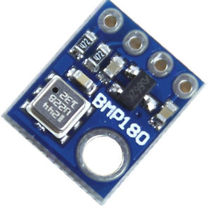
Barometric Pressure Sensor BMP180 Digital Board Module
BMP180 Digital Barometric Pressure Sensor Board Module Arduino Compatible Measuring the absolute pressure of the environment using a digital barometer such as this has some interesting applications. By converting the pressure measured into altitude, you have a reliable sensor for determining the height of your robot, plane or projectile! Using a sensor as capable as the BMP180 you can achieve an accuracy of 1m, with the noise of only 17cm in ultra-high resolution noise.The device will operate at the only 0.3uA meaning low current draw for battery-powered applications. The BMP180 comes fully calibrated and ready to use. As the device operates over I2C we’ve added optional I2C pull-ups that can be enabled using the PU (pull up) jumper on the board for your convenience and ease during breadboarding. Using I2C, the device provides pressure and temperature as 16bit values, which are used along with calibration data within the device are used to provide a temperature compensated altitude calculation.SKU: CE-M037 -
Motor Drives & controllers
SG90 9g Mini Servo 1.2kgCm – 180 degree Rotation
The SG90 mini servo is lightweight, It is standard Quality and lightning-fast servo, designed to work with almost all the radio control systems. It is with excellent performance and high torque of 1.5kg cm gives you the freedom to use it for a variety of projects. The SG90 mini servo with accessories is perfect for R/C helicopter, plane, car, boat and truck use.
SKU: CE-R001 -
Components, Transistors
2N3866A NPN RF Power Transistor – Metal Package
QUICK OVERVIEW
- RF & MICROWAVE DISCRETE LOW POWER TRANSISTORS
- Silicon NPN, To-39 packaged VHF/UHF Transistor
- Specified 400 MHz, 28Vdc Characteristics
– Output Power = 1.0 Watt
– Minimum Gain = 10 dB
– Efficiency = 45% - 800 MHz Current-Gain Bandwidth Product
For Download Datasheet Please click bellow link
https://datasheetspdf.com/pdf-file/1114831/Motorola/2N3866A/1
SKU: CE-MT700 -
Components
SN74HC595N, 8-Bit Shift Register ICs
Features:
- 8-bit
- Logic Family : HC
- Logical Function : Shift Register
- Operating Supply Voltage (Typ) : 5V
- Output Type : 3-State
- Package Type : DIP
- Propagation Delay Time : 265ns
- Operating Temp Range : -40C to 125C
- Operating Supply Voltage (Min) : 2V
- Operating Supply Voltage (Max) : 6V
You Will Get :
- SN74HC595N IC = 1
- 16 Pin IC Base = 1
SKU: CE-IC004 -
Developments Boards
Arduino UNO R3 Atmega16U2 With Cable
The Arduino Uno R3 is a micro-controller board base on the ATmega328. It has 14 digital input/output pins (of which 6 can be used as PWM outputs); 6 analog inputs, a 16 MHz ceramic resonator, a USB connection, a power jack, an ICSP header, and a reset button. It contains everything need to support the micro-controller; simply connect it to a computer with a USB cable or power it with a AC-to-DC adapter or battery to get start.
The Arduino Uno R3 differs from all preceding boards in that it does not use the FTDI USB-to-serial driver chip. Instead, it features the Atmega16U2 (Atmega8U2 up to version R2) program as a USB-to-serial converter. Revision 2 of the Uno board has a resistor pulling the 8U2 HWB line to ground, making it easier to put into DFU mode.
“Uno” means one in Italian and is name to mark the upcoming release of Arduino 1.0. The Uno and version 1.0 will be the reference versions of Arduino, moving forward. The Uno is the latest in a series of USB Arduino boards, and the reference model for the Arduino platform; for a comparison with previous versions, see the index of Arduino boards.
Note: The Arduino Uno R3 reference design can use an Atmega8, 168, or 328, Current models use an ATmega328, but an Atmega8 is shown in the schematic for reference. The pin configuration is identical on all three processors.
Power :
The Arduino Uno R3 can be powered via the USB connection or with an external power supply. The power source is selected automatically.
External (non-USB) power can come either from an AC-to-DC adapter (wall-wart) or battery. The adapter can be connected by plugging a 2.1mm center-positive plug into the board’s power jack. Leads from a battery can be inserted in the Gnd and Vin pin headers of the POWER connector.
The board can operate on an external supply of 6 to 20 volts. If supplied with less than 7V, however, the 5V pin may supply less than five volts and the board may be unstable. If using more than 12V, the voltage regulator may overheat and damage the board. The recommended range is 7 to 12 volts.
The power pins are as follows :
- VIN. The input voltage to the Arduino board when it’s using an external power source (as opposed to 5 volts from the USB connection or other regulated power source). You can supply voltage through this pin, or, if supplying voltage via the power jack, access it through this pin.
- 5V.This pin outputs a regulated 5V from the regulator on the board. The board can be supplied with power either from the DC power jack (7 – 12V), the USB connector (5V), or the VIN pin of the board (7-12V). Supplying voltage via the 5V or 3.3V pins bypasses the regulator, and can damage your board. We don’t advise it.
- 3V3. A 3.3 volt supply generated by the on-board regulator. Maximum current draw is 50 mA.
- GND. Ground pins.
- IOREF. This pin on the Arduino board provides the voltage reference with which the microcontroller operates. A properly configured shield can read the IOREF pin voltage and select the appropriate power source or enable voltage translators on the outputs for working with the 5V or 3.3V.
Memory :
The ATmega328 has 32 KB (with 0.5 KB used for the bootloader). It also has 2 KB of SRAM and 1 KB of EEPROM (which can be read and written with the EEPROM library).
Input and Output :
Each of the 14 digital pins on the Uno can be used as an input or output, using pinMode(), digitalWrite(), anddigitalRead() functions. They operate at 5 volts. Each pin can provide or receive a maximum of 40 mA and has an internal pull-up resistor (disconnected by default) of 20-50 kOhms. In addition, some pins have specialized functions:
- Serial: 0 (RX) and 1 (TX). Used to receive (RX) and transmit (TX) TTL serial data. These pins are connected to the corresponding pins of the ATmega8U2 USB-to-TTL Serial chip.
- External Interrupts: 2 and 3. These pins can be configured to trigger an interrupt on a low value, a rising or falling edge, or a change in value. See the attachInterrupt() function for details.
- PWM: 3, 5, 6, 9, 10, and 11. Provide 8-bit PWM output with the analogWrite() function.
- SPI: 10 (SS), 11 (MOSI), 12 (MISO), 13 (SCK). These pins support SPI communication using the SPI library.
- LED: 13. There is a built-in LED connected to digital pin 13. When the pin is HIGH value, the LED is on, when the pin is LOW, it’s off.
The Arduino Uno R3 has 6 analog inputs, labeled A0 through A5, each of which provide 10 bits of resolution (i.e. 1024 different values). By default they measure from ground to 5 volts, though is it possible to change the upper end of their range using the AREF pin and the analogReference() function. Additionally, some pins have specialized functionality:
- TWI: A4 or SDA pin and A5 or SCL pin. Support TWI communication using the Wire library.
There are a couple of other pins on the board:
- AREF. Reference voltage for the analog inputs. Used with analogReference().
- Reset. Bring this line LOW to reset the microcontroller. Typically used to add a reset button to shields which block the one on the board.
See also the mapping between Arduino pins and ATmega328 ports. The mapping for the Atmega8, 168, and 328 is identical.
Communication :
The Arduino Uno R3 has a number of facilities for communicating with a computer, another Arduino, or other microcontrollers. The ATmega328 provides UART TTL (5V) serial communication, which is available on digital pins 0 (RX) and 1 (TX). An ATmega16U2 on the board channels this serial communication over USB and appears as a virtual com port to software on the computer. The ’16U2 firmware uses the standard USB COM drivers, and no external driver is needed. However, on Windows, a .inf file is required. The Arduino software includes a serial monitor which allows simple textual data to be sent to and from the Arduino board. The RX and TX LEDs on the board will flash when data is being transmitted via the USB-to-serial chip and USB connection to the computer (but not for serial communication on pins 0 and 1).
A SoftwareSerial library allows for serial communication on any of the Uno’s digital pins.
The ATmega328 also supports I2C (TWI) and SPI communication. The Arduino Uno R3 software includes a Wire library to simplify use of the I2C bus; see the documentation for details. For SPI communication, use the SPI library.
Programming :
The Arduino Uno R3 can be program with the Arduino software (download). Select “Arduino Uno from the Tools > Board menu (according to the micro-controller on your board). For details, see the reference and tutorials.
The ATmega328 on the Arduino Uno R3 comes pre burn with a bootloader that allows you to upload new code to it without the use of an external hardware programmer. It communicates using the original STK500 protocol (reference, C header files).
You can also bypass the bootloader and program the microcontroller through the ICSP (In-Circuit Serial Programming) header; see these instructions for details.
The ATmega16U2 (or 8U2 in the rev1 and rev2 boards) firmware source code is available . The ATmega16U2/8U2 is load with a DFU bootloader, which can be activate by:
- On Rev1 boards: connecting the solder jumper on the back of the board (near the map of Italy) and then resetting the 8U2.
- On Rev2 or later boards: there is a resistor that pulling the 8U2/16U2 HWB line to ground, making it easier to put into DFU mode.
You can then use Atmel’s FLIP software (Windows) or the DFU programmer (Mac OS X and Linux) to load a new firmware. Or you can use the ISP header with an external programmer (overwriting the DFU bootloader). See this user-contributed tutorial for more information.
Automatic (Software) Reset :
Rather than requiring a physical press of the reset button before an upload, the Arduino Uno is design in a way that allows it to be reset by software running on a connect computer. One of the hardware flow control lines (DTR) of theATmega8U2/16U2 is connected to the reset line of the ATmega328 via a 100 nano-farad capacitor. When this line is assert (taken low), the reset line drops long enough to reset the chip. The Arduino software uses this capability to allow you to upload code by simply pressing the upload button in the Arduino environment. This means that the boot-loader can have a shorter timeout, as the lowering of DTR can be well-coordinate with the start of the upload.
This setup has other implications. When the Uno is connect to either a computer running Mac OS X or Linux, it resets each time a connection is made to it from software (via USB). For the following half-second or so, the boot-loader is running on the Uno. While it is program to ignore malformed data (i.e. anything besides an upload of new code), it will intercept the first few bytes of data sent to the board after a connection is open. If a sketch running on the board receives one-time configuration or other data when it first starts, make sure that the software with which it communicates waits a second after opening the connection and before sending this data.
The Arduino Uno R3 contains a trace that can be cut to disable the auto-reset. The pads on either side of the trace can be soldere together to re-enable it. It’s label “RESET-EN”. You may also be able to disable the auto-reset by connecting a 110 ohm resistor from 5V to the reset line; see this forum thread for details.
USB Overcurrent Protection :
The Arduino Uno has a resettable polyfuse that protects your computer’s USB ports from shorts and overcurrent. Although most computers provide their own internal protection, the fuse provides an extra layer of protection. If more than 500 mA is apply to the USB port, the fuse will automatically break the connection until the short or overload is remove.
Physical Characteristics :
The maximum length and width of the Uno PCB are 2.7 and 2.1 inches respectively, with the USB connector and power jack extending beyond the former dimension. Four screw holes allow the board to be attache to a surface or case. Note that the distance between digital pins 7 and 8 is 160 mil (0.16″), not an even multiple of the 100 mil spacing of the other pins.
Package Includes :
1 x Arduino Uno R3.
1 x USB Cable.
Specifications and Features :
- Micro-controller : ATmega328
- Operating Voltage : 5V
- Input Voltage (recommended) : 7-12V
- Input Voltage (limits) : 6-20V
- Digital I/O Pins : 14 (of which 6 provide PWM output)
- Analog Input Pins : 6
- DC Current per I/O Pin : 40 mA
- DC Current for 3.3V Pin : 50 mA
- Flash Memory : 32 KB (ATmega328) of which 0.5 KB used by bootloader
- SRAM : 2 KB (ATmega328)
- EEPROM: 1 KB (ATmega328)
- Clock Speed: 16 MHz.
- 1.0 pinout : added SDA and SCL pins that are near to the AREF pin and two other new pins place near to the RESET pin, the IOREF that allow the shields to adapt to the voltage provide from the board. In future, shields will be compatible with both the board that uses the AVR, which operates with 5V and with the Arduino Due that operates with 3.3V. The second one is a not connect pin, that is reserve for future purposes.
- Stronger RESET circuit.
- Atmega 16U2 replace the 8U2.
SKU: CE-A005 -
Developments Boards
STM32F103C8T6-ARM-STM32-Minimum-System-Development-Board
This is STM32F103C8T6 Minimum System Board Microcomputer STM32 ARM Core Board. This board is low cost Minimum System Development Board for ARM Microcontroller STM32F103C8T6. Board is suitable for learners that want to learn STM32 microcontroller with ARM Coretex-M3 32-bit core.
SKU: CE-D002

-
Batteries, Batteries & Chargers
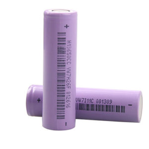
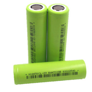
Li-Ion 18650 Rechargeable Battery 1200MAH
This is 1200 mAh Li-Ion Rechargeable cell is good quality Product. We are providing good Rechargeable Li-ion 18650 Cell at the best price in the market for our retail and bulk customers. These are powerful cells with a higher number of life cycles and charging capacity compared to other cells. It tested & guaranteed 1200mAh capacity. So many sellers selling the same looks batteries & claim Samsung Original.
So please avoid those sellers. Just buy one pc from us & try it out you can get the difference.
SKU: CE-B-18650-2-2 -
-
Circuits Boards & PCB, Tooles & Instruments
High Voltage Generator 5000-10000 volts
High Voltage Generator 5000-10000 volts.This consist an electric fence in the bat portion which has 5000-10,000 volts passing through them. This is not only mosquito repellent, it’s insect zapper. When a mosquito gets in contact the high voltage burns it. The inner circuit consists of battery, a charging unit, and a HV inverter circuit, which I’m going to describe here. It Can Use As mosquito killing Bat circuit
SKU: CE-T048 -
Circuits Boards & PCB, Tooles & Instruments
Breadboard MB102 830 Points for Solderless Prototype PCB
Breadboards are one of the most fundamental pieces when learning how to build circuits. In this tutorial, you will learn a little bit about what breadboards are, why they are called breadboards, and how to use one. Once you are done you should have a basic understanding of how breadboards work and be able to build a basic circuit on a breadboard. An MB102 830 Points Solderless Prototype PCB Breadboard.
SKU: CE-M0148


Products Grid
-
Modules & Sensors
Barometric Pressure Sensor BMP180 Digital Board Module
BMP180 Digital Barometric Pressure Sensor Board Module Arduino Compatible Measuring the absolute pressure of the environment using a digital barometer such as this has some interesting applications. By converting the pressure measured into altitude, you have a reliable sensor for determining the height of your robot, plane or projectile! Using a sensor as capable as the BMP180 you can achieve an accuracy of 1m, with the noise of only 17cm in ultra-high resolution noise.The device will operate at the only 0.3uA meaning low current draw for battery-powered applications. The BMP180 comes fully calibrated and ready to use. As the device operates over I2C we’ve added optional I2C pull-ups that can be enabled using the PU (pull up) jumper on the board for your convenience and ease during breadboarding. Using I2C, the device provides pressure and temperature as 16bit values, which are used along with calibration data within the device are used to provide a temperature compensated altitude calculation.SKU: CE-M037 -
Motor Drives & controllers
SG90 9g Mini Servo 1.2kgCm – 180 degree Rotation
The SG90 mini servo is lightweight, It is standard Quality and lightning-fast servo, designed to work with almost all the radio control systems. It is with excellent performance and high torque of 1.5kg cm gives you the freedom to use it for a variety of projects. The SG90 mini servo with accessories is perfect for R/C helicopter, plane, car, boat and truck use.
SKU: CE-R001 -
Components, Transistors
2N3866A NPN RF Power Transistor – Metal Package
QUICK OVERVIEW
- RF & MICROWAVE DISCRETE LOW POWER TRANSISTORS
- Silicon NPN, To-39 packaged VHF/UHF Transistor
- Specified 400 MHz, 28Vdc Characteristics
– Output Power = 1.0 Watt
– Minimum Gain = 10 dB
– Efficiency = 45% - 800 MHz Current-Gain Bandwidth Product
For Download Datasheet Please click bellow link
https://datasheetspdf.com/pdf-file/1114831/Motorola/2N3866A/1
SKU: CE-MT700 -
Components
SN74HC595N, 8-Bit Shift Register ICs
Features:
- 8-bit
- Logic Family : HC
- Logical Function : Shift Register
- Operating Supply Voltage (Typ) : 5V
- Output Type : 3-State
- Package Type : DIP
- Propagation Delay Time : 265ns
- Operating Temp Range : -40C to 125C
- Operating Supply Voltage (Min) : 2V
- Operating Supply Voltage (Max) : 6V
You Will Get :
- SN74HC595N IC = 1
- 16 Pin IC Base = 1
SKU: CE-IC004
-

 Developments Boards
Arduino UNO R3 Atmega16U2 With Cable
The Arduino Uno R3 is a micro-controller board base on the ATmega328. It has 14 digital input/output pins (of which 6 can be used as PWM outputs); 6 analog inputs, a 16 MHz ceramic resonator, a USB connection, a power jack, an ICSP header, and a reset button. It contains everything need to support the micro-controller; simply connect it to a computer with a USB cable or power it with a AC-to-DC adapter or battery to get start.
The Arduino Uno R3 differs from all preceding boards in that it does not use the FTDI USB-to-serial driver chip. Instead, it features the Atmega16U2 (Atmega8U2 up to version R2) program as a USB-to-serial converter. Revision 2 of the Uno board has a resistor pulling the 8U2 HWB line to ground, making it easier to put into DFU mode.
“Uno” means one in Italian and is name to mark the upcoming release of Arduino 1.0. The Uno and version 1.0 will be the reference versions of Arduino, moving forward. The Uno is the latest in a series of USB Arduino boards, and the reference model for the Arduino platform; for a comparison with previous versions, see the index of Arduino boards.
Note: The Arduino Uno R3 reference design can use an Atmega8, 168, or 328, Current models use an ATmega328, but an Atmega8 is shown in the schematic for reference. The pin configuration is identical on all three processors.
Power :
The Arduino Uno R3 can be powered via the USB connection or with an external power supply. The power source is selected automatically.
External (non-USB) power can come either from an AC-to-DC adapter (wall-wart) or battery. The adapter can be connected by plugging a 2.1mm center-positive plug into the board’s power jack. Leads from a battery can be inserted in the Gnd and Vin pin headers of the POWER connector.
The board can operate on an external supply of 6 to 20 volts. If supplied with less than 7V, however, the 5V pin may supply less than five volts and the board may be unstable. If using more than 12V, the voltage regulator may overheat and damage the board. The recommended range is 7 to 12 volts.
The power pins are as follows :
- VIN. The input voltage to the Arduino board when it’s using an external power source (as opposed to 5 volts from the USB connection or other regulated power source). You can supply voltage through this pin, or, if supplying voltage via the power jack, access it through this pin.
- 5V.This pin outputs a regulated 5V from the regulator on the board. The board can be supplied with power either from the DC power jack (7 – 12V), the USB connector (5V), or the VIN pin of the board (7-12V). Supplying voltage via the 5V or 3.3V pins bypasses the regulator, and can damage your board. We don’t advise it.
- 3V3. A 3.3 volt supply generated by the on-board regulator. Maximum current draw is 50 mA.
- GND. Ground pins.
- IOREF. This pin on the Arduino board provides the voltage reference with which the microcontroller operates. A properly configured shield can read the IOREF pin voltage and select the appropriate power source or enable voltage translators on the outputs for working with the 5V or 3.3V.
Memory :
The ATmega328 has 32 KB (with 0.5 KB used for the bootloader). It also has 2 KB of SRAM and 1 KB of EEPROM (which can be read and written with the EEPROM library).
Input and Output :
Each of the 14 digital pins on the Uno can be used as an input or output, using pinMode(), digitalWrite(), anddigitalRead() functions. They operate at 5 volts. Each pin can provide or receive a maximum of 40 mA and has an internal pull-up resistor (disconnected by default) of 20-50 kOhms. In addition, some pins have specialized functions:
- Serial: 0 (RX) and 1 (TX). Used to receive (RX) and transmit (TX) TTL serial data. These pins are connected to the corresponding pins of the ATmega8U2 USB-to-TTL Serial chip.
- External Interrupts: 2 and 3. These pins can be configured to trigger an interrupt on a low value, a rising or falling edge, or a change in value. See the attachInterrupt() function for details.
- PWM: 3, 5, 6, 9, 10, and 11. Provide 8-bit PWM output with the analogWrite() function.
- SPI: 10 (SS), 11 (MOSI), 12 (MISO), 13 (SCK). These pins support SPI communication using the SPI library.
- LED: 13. There is a built-in LED connected to digital pin 13. When the pin is HIGH value, the LED is on, when the pin is LOW, it’s off.
The Arduino Uno R3 has 6 analog inputs, labeled A0 through A5, each of which provide 10 bits of resolution (i.e. 1024 different values). By default they measure from ground to 5 volts, though is it possible to change the upper end of their range using the AREF pin and the analogReference() function. Additionally, some pins have specialized functionality:
- TWI: A4 or SDA pin and A5 or SCL pin. Support TWI communication using the Wire library.
There are a couple of other pins on the board:
- AREF. Reference voltage for the analog inputs. Used with analogReference().
- Reset. Bring this line LOW to reset the microcontroller. Typically used to add a reset button to shields which block the one on the board.
See also the mapping between Arduino pins and ATmega328 ports. The mapping for the Atmega8, 168, and 328 is identical.
Communication :
The Arduino Uno R3 has a number of facilities for communicating with a computer, another Arduino, or other microcontrollers. The ATmega328 provides UART TTL (5V) serial communication, which is available on digital pins 0 (RX) and 1 (TX). An ATmega16U2 on the board channels this serial communication over USB and appears as a virtual com port to software on the computer. The ’16U2 firmware uses the standard USB COM drivers, and no external driver is needed. However, on Windows, a .inf file is required. The Arduino software includes a serial monitor which allows simple textual data to be sent to and from the Arduino board. The RX and TX LEDs on the board will flash when data is being transmitted via the USB-to-serial chip and USB connection to the computer (but not for serial communication on pins 0 and 1).
A SoftwareSerial library allows for serial communication on any of the Uno’s digital pins.
The ATmega328 also supports I2C (TWI) and SPI communication. The Arduino Uno R3 software includes a Wire library to simplify use of the I2C bus; see the documentation for details. For SPI communication, use the SPI library.
Programming :
The Arduino Uno R3 can be program with the Arduino software (download). Select “Arduino Uno from the Tools > Board menu (according to the micro-controller on your board). For details, see the reference and tutorials.
The ATmega328 on the Arduino Uno R3 comes pre burn with a bootloader that allows you to upload new code to it without the use of an external hardware programmer. It communicates using the original STK500 protocol (reference, C header files).
You can also bypass the bootloader and program the microcontroller through the ICSP (In-Circuit Serial Programming) header; see these instructions for details.
The ATmega16U2 (or 8U2 in the rev1 and rev2 boards) firmware source code is available . The ATmega16U2/8U2 is load with a DFU bootloader, which can be activate by:
- On Rev1 boards: connecting the solder jumper on the back of the board (near the map of Italy) and then resetting the 8U2.
- On Rev2 or later boards: there is a resistor that pulling the 8U2/16U2 HWB line to ground, making it easier to put into DFU mode.
You can then use Atmel’s FLIP software (Windows) or the DFU programmer (Mac OS X and Linux) to load a new firmware. Or you can use the ISP header with an external programmer (overwriting the DFU bootloader). See this user-contributed tutorial for more information.
Automatic (Software) Reset :
Rather than requiring a physical press of the reset button before an upload, the Arduino Uno is design in a way that allows it to be reset by software running on a connect computer. One of the hardware flow control lines (DTR) of theATmega8U2/16U2 is connected to the reset line of the ATmega328 via a 100 nano-farad capacitor. When this line is assert (taken low), the reset line drops long enough to reset the chip. The Arduino software uses this capability to allow you to upload code by simply pressing the upload button in the Arduino environment. This means that the boot-loader can have a shorter timeout, as the lowering of DTR can be well-coordinate with the start of the upload.
This setup has other implications. When the Uno is connect to either a computer running Mac OS X or Linux, it resets each time a connection is made to it from software (via USB). For the following half-second or so, the boot-loader is running on the Uno. While it is program to ignore malformed data (i.e. anything besides an upload of new code), it will intercept the first few bytes of data sent to the board after a connection is open. If a sketch running on the board receives one-time configuration or other data when it first starts, make sure that the software with which it communicates waits a second after opening the connection and before sending this data.
The Arduino Uno R3 contains a trace that can be cut to disable the auto-reset. The pads on either side of the trace can be soldere together to re-enable it. It’s label “RESET-EN”. You may also be able to disable the auto-reset by connecting a 110 ohm resistor from 5V to the reset line; see this forum thread for details.
USB Overcurrent Protection :
The Arduino Uno has a resettable polyfuse that protects your computer’s USB ports from shorts and overcurrent. Although most computers provide their own internal protection, the fuse provides an extra layer of protection. If more than 500 mA is apply to the USB port, the fuse will automatically break the connection until the short or overload is remove.
Physical Characteristics :
The maximum length and width of the Uno PCB are 2.7 and 2.1 inches respectively, with the USB connector and power jack extending beyond the former dimension. Four screw holes allow the board to be attache to a surface or case. Note that the distance between digital pins 7 and 8 is 160 mil (0.16″), not an even multiple of the 100 mil spacing of the other pins.
Package Includes :
1 x Arduino Uno R3.
1 x USB Cable.
Specifications and Features :
- Micro-controller : ATmega328
- Operating Voltage : 5V
- Input Voltage (recommended) : 7-12V
- Input Voltage (limits) : 6-20V
- Digital I/O Pins : 14 (of which 6 provide PWM output)
- Analog Input Pins : 6
- DC Current per I/O Pin : 40 mA
- DC Current for 3.3V Pin : 50 mA
- Flash Memory : 32 KB (ATmega328) of which 0.5 KB used by bootloader
- SRAM : 2 KB (ATmega328)
- EEPROM: 1 KB (ATmega328)
- Clock Speed: 16 MHz.
- 1.0 pinout : added SDA and SCL pins that are near to the AREF pin and two other new pins place near to the RESET pin, the IOREF that allow the shields to adapt to the voltage provide from the board. In future, shields will be compatible with both the board that uses the AVR, which operates with 5V and with the Arduino Due that operates with 3.3V. The second one is a not connect pin, that is reserve for future purposes.
- Stronger RESET circuit.
- Atmega 16U2 replace the 8U2.
SKU: CE-A005
-
Developments Boards
STM32F103C8T6-ARM-STM32-Minimum-System-Development-Board
This is STM32F103C8T6 Minimum System Board Microcomputer STM32 ARM Core Board. This board is low cost Minimum System Development Board for ARM Microcontroller STM32F103C8T6. Board is suitable for learners that want to learn STM32 microcontroller with ARM Coretex-M3 32-bit core.
SKU: CE-D002 -
Modules & Sensors
BMP280 Pressure Sensor Module High Precision Atmospheric
- Bosch has stepped up their game with their new BMP280 sensor, an environmental sensor with temperature, barometric pressure that is the next generation upgrade to the BMP085/BMP180/BMP183. This sensor is great for all sorts of weather sensing and can even be used in both I2C and SPI!
- This precision sensor from Bosch is the best low-cost, precision sensing solution for measuring barometric pressure with ±1 hPa absolute accuracy, and temperature with ±1.0°C accuracy. Because pressure changes with altitude, and the pressure measurements are so good, you can also use it as an altimeter with ±1 meter accuracy
SKU: CE-M036 -
Modules & Sensors
Digital Thermal Sensor Module Temperature Sensor Module
- 100% Brand New and High Quality
- the thermal resistance of the module is very sensitive to the ambient temperature , generally used to detect the ambient temperature ;
- through the adjustment of the potentiometer , can change the temperature detection threshold (ie, temperature control value) if necessary to control the ambient temperature is 50 degrees , the module in the corresponding ambient temperature to which the green light , DO output is HIGH level falls below the set temperature value, the output is high , the green light does not shine ;
- DO output can be directly connected with the microcontroller through the microcontroller to detect high and low , thereby detecting the ambient temperature changes ;
- DO OUR outputs can directly drive the relay module , which can be composed of a thermostat to control the operating temperature of related equipment can also be connected to the fan used to heat and other ;
- the detection range of the module’s temperature 20-80 °C ;
- this module can also be replaced with a wire temperature sensor for water temperature, water tank controlled.
SKU: CE-M041 -
Motor Drives & controllers
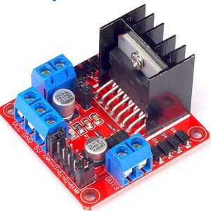
L298N DC Motor Driver Controller 2A Stepper Motor Board Module
The L298N driver module, using ST’s L298N chip can directly drive two 3-30V DC motor, and provides a 5V output interface can 5V single-chip circuitry to supply, support 3.3VMCU control, you can easily control the DC motor speed and direction, you can also control the 2-phase stepper motor, smart car essential. Using L298N made by ST company as the control chip,the module has such characteristics as strong driving ability, low calorific value and strong anti-interference ability.
SKU: CE-M084

Best Sellers
-
 Basic LED, LED & Lights, SMD
1206 SMD Led Super Bright Red/Green/Blue/Yellow/White/Jade Green
Price range: ₹1.77 through ₹2.36 Price Including GST This product has multiple variants. The options may be chosen on the product page -
 Circuits Boards & PCB, Tooles & Instruments
Heat Shrink Tube assorted Size 1 Meter
Price range: ₹5.90 through ₹41.30 Price Including GST This product has multiple variants. The options may be chosen on the product page -
-
 Components, Resistance
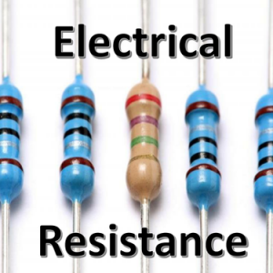
Metal film resistor 1/4 Watt multiple value of resistance
₹1.18 Price Including GST This product has multiple variants. The options may be chosen on the product page -
 Holders Wire connector Cables & Screw, Tooles & Instruments
Self Thread Screw Star Head Assorted Size
Price range: ₹1.18 through ₹2.36 Price Including GST This product has multiple variants. The options may be chosen on the product page

-
 Decorative LED, LED & Lights, Solar & Lights
3 LED strips 12V Waterproof 5630/5730 SMD Injection module
₹11.20 Price Including GST This product has multiple variants. The options may be chosen on the product page -
-
 LED & Lights, SMD
5730/5630 SMD LED Light Emitting Diode Green & Blue
₹3.54 Price Including GST This product has multiple variants. The options may be chosen on the product page -


Added
Barometric Pressure Sensor BMP180 Digital Board Module

Digispark ATTiny85 USB Development Board Digistump
SG90 9g Mini Servo 1.2kgCm – 180 degree Rotation
The SG90 mini servo is lightweight, It is standard Quality and lightning-fast servo, designed to work with almost all the radio control systems. It is with excellent performance and high torque of 1.5kg cm gives you the freedom to use it for a variety of projects. The SG90 mini servo with accessories is perfect for R/C helicopter, plane, car, boat and truck use.
HX711 Weighing Sensor Dual-Channel 24 Bit Precision A/D Module Pressure Sensor
Features:
2N3866A NPN RF Power Transistor – Metal Package
QUICK OVERVIEW
– Output Power = 1.0 Watt
– Minimum Gain = 10 dB
– Efficiency = 45%
For Download Datasheet Please click bellow link
https://datasheetspdf.com/pdf-file/1114831/Motorola/2N3866A/1
SN74HC595N, 8-Bit Shift Register ICs
Features:
You Will Get :
Arduino UNO R3 Atmega16U2 With Cable
The Arduino Uno R3 is a micro-controller board base on the ATmega328. It has 14 digital input/output pins (of which 6 can be used as PWM outputs); 6 analog inputs, a 16 MHz ceramic resonator, a USB connection, a power jack, an ICSP header, and a reset button. It contains everything need to support the micro-controller; simply connect it to a computer with a USB cable or power it with a AC-to-DC adapter or battery to get start.
The Arduino Uno R3 differs from all preceding boards in that it does not use the FTDI USB-to-serial driver chip. Instead, it features the Atmega16U2 (Atmega8U2 up to version R2) program as a USB-to-serial converter. Revision 2 of the Uno board has a resistor pulling the 8U2 HWB line to ground, making it easier to put into DFU mode.
“Uno” means one in Italian and is name to mark the upcoming release of Arduino 1.0. The Uno and version 1.0 will be the reference versions of Arduino, moving forward. The Uno is the latest in a series of USB Arduino boards, and the reference model for the Arduino platform; for a comparison with previous versions, see the index of Arduino boards.
Note: The Arduino Uno R3 reference design can use an Atmega8, 168, or 328, Current models use an ATmega328, but an Atmega8 is shown in the schematic for reference. The pin configuration is identical on all three processors.
Power :
The Arduino Uno R3 can be powered via the USB connection or with an external power supply. The power source is selected automatically.
External (non-USB) power can come either from an AC-to-DC adapter (wall-wart) or battery. The adapter can be connected by plugging a 2.1mm center-positive plug into the board’s power jack. Leads from a battery can be inserted in the Gnd and Vin pin headers of the POWER connector.
The board can operate on an external supply of 6 to 20 volts. If supplied with less than 7V, however, the 5V pin may supply less than five volts and the board may be unstable. If using more than 12V, the voltage regulator may overheat and damage the board. The recommended range is 7 to 12 volts.
The power pins are as follows :
Memory :
The ATmega328 has 32 KB (with 0.5 KB used for the bootloader). It also has 2 KB of SRAM and 1 KB of EEPROM (which can be read and written with the EEPROM library).
Input and Output :
Each of the 14 digital pins on the Uno can be used as an input or output, using pinMode(), digitalWrite(), anddigitalRead() functions. They operate at 5 volts. Each pin can provide or receive a maximum of 40 mA and has an internal pull-up resistor (disconnected by default) of 20-50 kOhms. In addition, some pins have specialized functions:
The Arduino Uno R3 has 6 analog inputs, labeled A0 through A5, each of which provide 10 bits of resolution (i.e. 1024 different values). By default they measure from ground to 5 volts, though is it possible to change the upper end of their range using the AREF pin and the analogReference() function. Additionally, some pins have specialized functionality:
There are a couple of other pins on the board:
See also the mapping between Arduino pins and ATmega328 ports. The mapping for the Atmega8, 168, and 328 is identical.
Communication :
The Arduino Uno R3 has a number of facilities for communicating with a computer, another Arduino, or other microcontrollers. The ATmega328 provides UART TTL (5V) serial communication, which is available on digital pins 0 (RX) and 1 (TX). An ATmega16U2 on the board channels this serial communication over USB and appears as a virtual com port to software on the computer. The ’16U2 firmware uses the standard USB COM drivers, and no external driver is needed. However, on Windows, a .inf file is required. The Arduino software includes a serial monitor which allows simple textual data to be sent to and from the Arduino board. The RX and TX LEDs on the board will flash when data is being transmitted via the USB-to-serial chip and USB connection to the computer (but not for serial communication on pins 0 and 1).
A SoftwareSerial library allows for serial communication on any of the Uno’s digital pins.
The ATmega328 also supports I2C (TWI) and SPI communication. The Arduino Uno R3 software includes a Wire library to simplify use of the I2C bus; see the documentation for details. For SPI communication, use the SPI library.
Programming :
The Arduino Uno R3 can be program with the Arduino software (download). Select “Arduino Uno from the Tools > Board menu (according to the micro-controller on your board). For details, see the reference and tutorials.
The ATmega328 on the Arduino Uno R3 comes pre burn with a bootloader that allows you to upload new code to it without the use of an external hardware programmer. It communicates using the original STK500 protocol (reference, C header files).
You can also bypass the bootloader and program the microcontroller through the ICSP (In-Circuit Serial Programming) header; see these instructions for details.
The ATmega16U2 (or 8U2 in the rev1 and rev2 boards) firmware source code is available . The ATmega16U2/8U2 is load with a DFU bootloader, which can be activate by:
You can then use Atmel’s FLIP software (Windows) or the DFU programmer (Mac OS X and Linux) to load a new firmware. Or you can use the ISP header with an external programmer (overwriting the DFU bootloader). See this user-contributed tutorial for more information.
Automatic (Software) Reset :
Rather than requiring a physical press of the reset button before an upload, the Arduino Uno is design in a way that allows it to be reset by software running on a connect computer. One of the hardware flow control lines (DTR) of theATmega8U2/16U2 is connected to the reset line of the ATmega328 via a 100 nano-farad capacitor. When this line is assert (taken low), the reset line drops long enough to reset the chip. The Arduino software uses this capability to allow you to upload code by simply pressing the upload button in the Arduino environment. This means that the boot-loader can have a shorter timeout, as the lowering of DTR can be well-coordinate with the start of the upload.
This setup has other implications. When the Uno is connect to either a computer running Mac OS X or Linux, it resets each time a connection is made to it from software (via USB). For the following half-second or so, the boot-loader is running on the Uno. While it is program to ignore malformed data (i.e. anything besides an upload of new code), it will intercept the first few bytes of data sent to the board after a connection is open. If a sketch running on the board receives one-time configuration or other data when it first starts, make sure that the software with which it communicates waits a second after opening the connection and before sending this data.
The Arduino Uno R3 contains a trace that can be cut to disable the auto-reset. The pads on either side of the trace can be soldere together to re-enable it. It’s label “RESET-EN”. You may also be able to disable the auto-reset by connecting a 110 ohm resistor from 5V to the reset line; see this forum thread for details.
USB Overcurrent Protection :
The Arduino Uno has a resettable polyfuse that protects your computer’s USB ports from shorts and overcurrent. Although most computers provide their own internal protection, the fuse provides an extra layer of protection. If more than 500 mA is apply to the USB port, the fuse will automatically break the connection until the short or overload is remove.
Physical Characteristics :
The maximum length and width of the Uno PCB are 2.7 and 2.1 inches respectively, with the USB connector and power jack extending beyond the former dimension. Four screw holes allow the board to be attache to a surface or case. Note that the distance between digital pins 7 and 8 is 160 mil (0.16″), not an even multiple of the 100 mil spacing of the other pins.
Package Includes :
1 x Arduino Uno R3.
1 x USB Cable.
Specifications and Features :
STM32F103C8T6-ARM-STM32-Minimum-System-Development-Board
This is STM32F103C8T6 Minimum System Board Microcomputer STM32 ARM Core Board. This board is low cost Minimum System Development Board for ARM Microcontroller STM32F103C8T6. Board is suitable for learners that want to learn STM32 microcontroller with ARM Coretex-M3 32-bit core.
BMP280 Pressure Sensor Module High Precision Atmospheric
Digital Thermal Sensor Module Temperature Sensor Module
L298N DC Motor Driver Controller 2A Stepper Motor Board Module
The L298N driver module, using ST’s L298N chip can directly drive two 3-30V DC motor, and provides a 5V output interface can 5V single-chip circuitry to supply, support 3.3VMCU control, you can easily control the DC motor speed and direction, you can also control the 2-phase stepper motor, smart car essential. Using L298N made by ST company as the control chip,the module has such characteristics as strong driving ability, low calorific value and strong anti-interference ability.
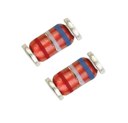
LL34 SMD Zener diode package 1/2W Multiple Value
SMD diodes LL34 have a range of anode/cathodeidentifiers. Sometimes it’s easiest to just use a multimeter to test for polarity. Turn the multimeter to the diode setting (usually indicated by a diodesymbol), and touch each probe to one of the LEDterminals. … Diodes certainly aren’t the only polarized component.

AMS1117-5.0V SOT-223 5V Fixed Linear Voltage Regulator (SMD)
AMS1117 is a series of low dropout three -terminal regulators with a dropout of 1.3V at 1A load current. AMS 1117 features a very low standby current 2mA compared to 5mA of competitor. Other than a fixed version, Vout = 1.2V, 1.5V, 1.8V, 2.5V, 3.3V, 5V, and 12V, AMS1117 has an adjustable version, which can provide an output voltage from 1.25 to 12V with only two external resistors. AMS 1117 offers thermal shut down and current limit functions, to assure the stability of chip and power system. And it uses trimming technique to guarantee output voltage accuracy within ±2%. Other output voltage accuracy can be customized on demand, such as ±1% AMS 1117 is available in SOT -223, TO-252 power package.
NRF24L01 with antenna V5.0 + PA + LNA wireless Module 1000 meters Long Range

NRF24L01 with antenna V5.0 + PA + LNA wireless Module 1000 meters Long Range
The NRF24L01 module is the latest in RF modules. This module uses the 2.4GHz transceiver from Nordic Semiconductor, the NRF24L01+. This transceiver IC operates in the 2.4GHz band and has many new features! Take all the coolness of the nRF2401A and add some extra pipelines, buffers, and an auto-retransmit feature – very nice!
This board features a reverse polarized SMA connector for maximum RF range. And there is PA and LNA circuit on board, with the external antenna it can reach long distance than the one without these parts.
This module comes with the 2.4G antenna (2DB), with 250Kbps transmission rate on open air it can reach the 800-1K meters communication distance.
Metal film resistor 1/4 Watt multiple value of resistance
Several Values Of Registers.You can Buy as per your requirement. Metal film resistors have a thin metal layer as resistive element on a non-conducting body. They are among the most common types of axial resistors. Other film type resistors are carbon film and thick and thin film resistors. In most literature referrals to metal film, usually it is a cylindrical axial resistor. However, thin film chip resistors use the same manufacturing principle for the metal layer. The appearance of metal film resistors is similar to carbon film resistors, but their properties for stability, accuracy and reliability are considerably better.
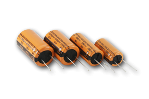
Electrolytic capacitors Assorted value Keltron
High purity Etched and Formed Aluminium foil with aluminium oxide dielectric barrier as anode foil and an aluminium cathode foil are concentrically wound with a layer of condenser grade paper in between and after impregnation with electrolyte, the wound element is housed in an Aluminium can and then hermetically sealed using a rubber bung to form an Aluminium electrolytic capacitor. The most important advantage of the electrolytic capacitors are the higher capacitance ratio to dimensions when compared with other capacitors. This is principally due to microscopically thin dielectric layer, which produces large capacitance per unit area. Over the years there have been continuous improvements in the etching technology of anode foil that has resulted in many fold increase in the actual anode surface area resulting in reduction in capacitor size. The oxide dielectric layer has rectifier properties blocking current flow in one direction but offering low resistance in the opposite direction. Reversal of more than two volts will cause breakdown of the film and detruction of the capacitor. So Electrolytic Capacitor for AC applications are specially manufactured and marked Non polar/AC. Others are polar Capacitors and there for limited to DC applications.
NPN Transistor variable range
In the previous tutorial we saw that the standard Bipolar Transistor or BJT, comes in two basic forms. An NPN (Negative-Positive-Negative) type and a PNP (<b”>Positive-Negative-Positive) type.</b”>
The most commonly used transistor configuration is the NPN Transistor. We also learnt that the junctions of the bipolar transistor can be biased in one of three different ways – Common Base, Common Emitter and Common Collector.
40 Pin male header Burge Strip Single Row / Double Row / L-type

40 Pin male header Burge Strip Single Row / Double Row / L-type
High Quality 40 pins 2.54mm male connector . You can get varieties & buy as per your requirement. It can be cut any size easily any size as per your necessity. Single Row Straight / Double row Straight / L type etc.
If you face any issue like payment fail or buying problem Please contact us Call Or Whatsapp :- + 91 9830150448

ST-Link V2 Mini STM8 STM32 Simulator Download Programmer
The ST-LINK/V2 is an in-circuit debugger and programmer for the STM8 and STM32 microcontroller families. The single wire interface module (SWIM) and JTAG/serial wire debugging (SWD) interfaces are used to communicate with any STM8 or STM32 microcontroller located on an application board.