Developments Boards
Showing 16–30 of 66 results
-
Developments Boards, Modules & Sensors
Alcohol Sensor MQ3 Module for all MCU
This is a simple to use MQ-3 Alcohol Detector Gas Sensor Module which can sense the presence of Alcohol in the air. The module uses our MQ-3 sensor. It simplifies the interface to the odd pin spacing of the sensor and provides an interface through standard 4 x 0.1″ header pins. It provides an analog output corresponding to the concentration of the gas in the air and an easy to use digital output. The onboard potentiometer can be used to set the maximum gas concentration beyond which the digital output gets triggered. Just power the module with 5V set the threshold and you can start getting the gas concentration of the air around the sensor! An onboard LED signals the presence of any gas. Perfect sensing alcohol concentration on your breath just likes common breathalyzer.
SKU: CE-M095 -
Developments Boards, Modules & Sensors, Robots & Kits
APDS-9930 Non-contact proximity and Ambient Light sensor
 Developments Boards, Modules & Sensors, Robots & Kits
APDS-9930 Non-contact proximity and Ambient Light sensor
APDS-9930 is a digital I2C compatible interface ambient light sensor (ALS) and proximity sensor with IR LED in a single 8-pin package. The ambient light sensor utilizes dual photodiodes to approximate the human eye response with a low lux performance at 0.01 lux. This high sensitivity allows for the device to operate behind a darkened glass. The proximity sensor is fully calibrated to detection of objects to 100 mm thus eliminating the need for factory calibration of the end equipment or sub-assembly. The proximity detection feature operates well from bright sunlight to dark rooms. The addition of the micro-optics lenses within the module, provide highly efficient transmission and reception of infrared energy which lowers overall power dissipation. In addition, an internal state machine provides the ability to put the device into a low power mode in between ALS and proximity measurements providing very low average power consumption.
SKU: CE-M088 -
Developments Boards
Arduino UNO R3 Atmega16U2 With Cable
The Arduino Uno R3 is a micro-controller board base on the ATmega328. It has 14 digital input/output pins (of which 6 can be used as PWM outputs); 6 analog inputs, a 16 MHz ceramic resonator, a USB connection, a power jack, an ICSP header, and a reset button. It contains everything need to support the micro-controller; simply connect it to a computer with a USB cable or power it with a AC-to-DC adapter or battery to get start.
The Arduino Uno R3 differs from all preceding boards in that it does not use the FTDI USB-to-serial driver chip. Instead, it features the Atmega16U2 (Atmega8U2 up to version R2) program as a USB-to-serial converter. Revision 2 of the Uno board has a resistor pulling the 8U2 HWB line to ground, making it easier to put into DFU mode.
“Uno” means one in Italian and is name to mark the upcoming release of Arduino 1.0. The Uno and version 1.0 will be the reference versions of Arduino, moving forward. The Uno is the latest in a series of USB Arduino boards, and the reference model for the Arduino platform; for a comparison with previous versions, see the index of Arduino boards.
Note: The Arduino Uno R3 reference design can use an Atmega8, 168, or 328, Current models use an ATmega328, but an Atmega8 is shown in the schematic for reference. The pin configuration is identical on all three processors.
Power :
The Arduino Uno R3 can be powered via the USB connection or with an external power supply. The power source is selected automatically.
External (non-USB) power can come either from an AC-to-DC adapter (wall-wart) or battery. The adapter can be connected by plugging a 2.1mm center-positive plug into the board’s power jack. Leads from a battery can be inserted in the Gnd and Vin pin headers of the POWER connector.
The board can operate on an external supply of 6 to 20 volts. If supplied with less than 7V, however, the 5V pin may supply less than five volts and the board may be unstable. If using more than 12V, the voltage regulator may overheat and damage the board. The recommended range is 7 to 12 volts.
The power pins are as follows :
- VIN. The input voltage to the Arduino board when it’s using an external power source (as opposed to 5 volts from the USB connection or other regulated power source). You can supply voltage through this pin, or, if supplying voltage via the power jack, access it through this pin.
- 5V.This pin outputs a regulated 5V from the regulator on the board. The board can be supplied with power either from the DC power jack (7 – 12V), the USB connector (5V), or the VIN pin of the board (7-12V). Supplying voltage via the 5V or 3.3V pins bypasses the regulator, and can damage your board. We don’t advise it.
- 3V3. A 3.3 volt supply generated by the on-board regulator. Maximum current draw is 50 mA.
- GND. Ground pins.
- IOREF. This pin on the Arduino board provides the voltage reference with which the microcontroller operates. A properly configured shield can read the IOREF pin voltage and select the appropriate power source or enable voltage translators on the outputs for working with the 5V or 3.3V.
Memory :
The ATmega328 has 32 KB (with 0.5 KB used for the bootloader). It also has 2 KB of SRAM and 1 KB of EEPROM (which can be read and written with the EEPROM library).
Input and Output :
Each of the 14 digital pins on the Uno can be used as an input or output, using pinMode(), digitalWrite(), anddigitalRead() functions. They operate at 5 volts. Each pin can provide or receive a maximum of 40 mA and has an internal pull-up resistor (disconnected by default) of 20-50 kOhms. In addition, some pins have specialized functions:
- Serial: 0 (RX) and 1 (TX). Used to receive (RX) and transmit (TX) TTL serial data. These pins are connected to the corresponding pins of the ATmega8U2 USB-to-TTL Serial chip.
- External Interrupts: 2 and 3. These pins can be configured to trigger an interrupt on a low value, a rising or falling edge, or a change in value. See the attachInterrupt() function for details.
- PWM: 3, 5, 6, 9, 10, and 11. Provide 8-bit PWM output with the analogWrite() function.
- SPI: 10 (SS), 11 (MOSI), 12 (MISO), 13 (SCK). These pins support SPI communication using the SPI library.
- LED: 13. There is a built-in LED connected to digital pin 13. When the pin is HIGH value, the LED is on, when the pin is LOW, it’s off.
The Arduino Uno R3 has 6 analog inputs, labeled A0 through A5, each of which provide 10 bits of resolution (i.e. 1024 different values). By default they measure from ground to 5 volts, though is it possible to change the upper end of their range using the AREF pin and the analogReference() function. Additionally, some pins have specialized functionality:
- TWI: A4 or SDA pin and A5 or SCL pin. Support TWI communication using the Wire library.
There are a couple of other pins on the board:
- AREF. Reference voltage for the analog inputs. Used with analogReference().
- Reset. Bring this line LOW to reset the microcontroller. Typically used to add a reset button to shields which block the one on the board.
See also the mapping between Arduino pins and ATmega328 ports. The mapping for the Atmega8, 168, and 328 is identical.
Communication :
The Arduino Uno R3 has a number of facilities for communicating with a computer, another Arduino, or other microcontrollers. The ATmega328 provides UART TTL (5V) serial communication, which is available on digital pins 0 (RX) and 1 (TX). An ATmega16U2 on the board channels this serial communication over USB and appears as a virtual com port to software on the computer. The ’16U2 firmware uses the standard USB COM drivers, and no external driver is needed. However, on Windows, a .inf file is required. The Arduino software includes a serial monitor which allows simple textual data to be sent to and from the Arduino board. The RX and TX LEDs on the board will flash when data is being transmitted via the USB-to-serial chip and USB connection to the computer (but not for serial communication on pins 0 and 1).
A SoftwareSerial library allows for serial communication on any of the Uno’s digital pins.
The ATmega328 also supports I2C (TWI) and SPI communication. The Arduino Uno R3 software includes a Wire library to simplify use of the I2C bus; see the documentation for details. For SPI communication, use the SPI library.
Programming :
The Arduino Uno R3 can be program with the Arduino software (download). Select “Arduino Uno from the Tools > Board menu (according to the micro-controller on your board). For details, see the reference and tutorials.
The ATmega328 on the Arduino Uno R3 comes pre burn with a bootloader that allows you to upload new code to it without the use of an external hardware programmer. It communicates using the original STK500 protocol (reference, C header files).
You can also bypass the bootloader and program the microcontroller through the ICSP (In-Circuit Serial Programming) header; see these instructions for details.
The ATmega16U2 (or 8U2 in the rev1 and rev2 boards) firmware source code is available . The ATmega16U2/8U2 is load with a DFU bootloader, which can be activate by:
- On Rev1 boards: connecting the solder jumper on the back of the board (near the map of Italy) and then resetting the 8U2.
- On Rev2 or later boards: there is a resistor that pulling the 8U2/16U2 HWB line to ground, making it easier to put into DFU mode.
You can then use Atmel’s FLIP software (Windows) or the DFU programmer (Mac OS X and Linux) to load a new firmware. Or you can use the ISP header with an external programmer (overwriting the DFU bootloader). See this user-contributed tutorial for more information.
Automatic (Software) Reset :
Rather than requiring a physical press of the reset button before an upload, the Arduino Uno is design in a way that allows it to be reset by software running on a connect computer. One of the hardware flow control lines (DTR) of theATmega8U2/16U2 is connected to the reset line of the ATmega328 via a 100 nano-farad capacitor. When this line is assert (taken low), the reset line drops long enough to reset the chip. The Arduino software uses this capability to allow you to upload code by simply pressing the upload button in the Arduino environment. This means that the boot-loader can have a shorter timeout, as the lowering of DTR can be well-coordinate with the start of the upload.
This setup has other implications. When the Uno is connect to either a computer running Mac OS X or Linux, it resets each time a connection is made to it from software (via USB). For the following half-second or so, the boot-loader is running on the Uno. While it is program to ignore malformed data (i.e. anything besides an upload of new code), it will intercept the first few bytes of data sent to the board after a connection is open. If a sketch running on the board receives one-time configuration or other data when it first starts, make sure that the software with which it communicates waits a second after opening the connection and before sending this data.
The Arduino Uno R3 contains a trace that can be cut to disable the auto-reset. The pads on either side of the trace can be soldere together to re-enable it. It’s label “RESET-EN”. You may also be able to disable the auto-reset by connecting a 110 ohm resistor from 5V to the reset line; see this forum thread for details.
USB Overcurrent Protection :
The Arduino Uno has a resettable polyfuse that protects your computer’s USB ports from shorts and overcurrent. Although most computers provide their own internal protection, the fuse provides an extra layer of protection. If more than 500 mA is apply to the USB port, the fuse will automatically break the connection until the short or overload is remove.
Physical Characteristics :
The maximum length and width of the Uno PCB are 2.7 and 2.1 inches respectively, with the USB connector and power jack extending beyond the former dimension. Four screw holes allow the board to be attache to a surface or case. Note that the distance between digital pins 7 and 8 is 160 mil (0.16″), not an even multiple of the 100 mil spacing of the other pins.
Package Includes :
1 x Arduino Uno R3.
1 x USB Cable.
Specifications and Features :
- Micro-controller : ATmega328
- Operating Voltage : 5V
- Input Voltage (recommended) : 7-12V
- Input Voltage (limits) : 6-20V
- Digital I/O Pins : 14 (of which 6 provide PWM output)
- Analog Input Pins : 6
- DC Current per I/O Pin : 40 mA
- DC Current for 3.3V Pin : 50 mA
- Flash Memory : 32 KB (ATmega328) of which 0.5 KB used by bootloader
- SRAM : 2 KB (ATmega328)
- EEPROM: 1 KB (ATmega328)
- Clock Speed: 16 MHz.
- 1.0 pinout : added SDA and SCL pins that are near to the AREF pin and two other new pins place near to the RESET pin, the IOREF that allow the shields to adapt to the voltage provide from the board. In future, shields will be compatible with both the board that uses the AVR, which operates with 5V and with the Arduino Due that operates with 3.3V. The second one is a not connect pin, that is reserve for future purposes.
- Stronger RESET circuit.
- Atmega 16U2 replace the 8U2.
SKU: CE-A005 -
Developments Boards
Arduino Pro Mini ATMEGA328P 3.3V/8MHz
The Pro Mini is a microcontroller board based on the ATmega328 for Arduino. With 14 digital input / output pins (of which 6 can be used as PWM outputs), 8 analog inputs, an on-board resonator, a reset button, and holes for mounting pin headers. Six pin header can be connected to an FTDI cable to provide USB power and communication to the board.
SKU: CE-A001 -
Components, Developments Boards, integrated circuit
ATMEGA328-PU with arduino Bootloader 2018 version
 Components, Developments Boards, integrated circuit
ATMEGA328-PU with arduino Bootloader 2018 version
Microchip Technology ATmega328 8-bit AVR® Microcontrollers (MCUs) are high-performance RISC-based devices that combine 32KB ISP Flash memory with read-while-write capabilities, 1KB EEPROM, 2KB SRAM, 23 general-purpose I/O lines, 32 general-purpose working registers, serial programmable USART, and more.ATmega328 MCUs execute powerful instructions in a single clock cycle, allowing the device to achieve throughputs approaching 1 MIPS per MHz while balancing power consumption and processing speed. These Microchip MCUs are designed for use in industrial automation and home and building automation.
SKU: IC001 -
Developments Boards, Modules & Sensors
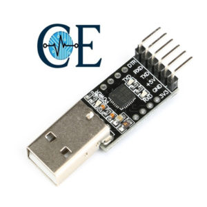
CP2102 USB to TTL USB UART converter module 6 Pin
Provides connection from USB on host computer to microcomputers or other TTL signal level accessories. The CP2102 Virtual COM Port (VCP) device drivers allow a CP2102-based device to appear to the PC’s application software as a COM port. Application software running on the PC accesses the CP2102-based device as it would access a standard hardware COM port
SKU: CE-M013 -
Developments Boards, Modules & Sensors
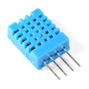
DHT-11 Digital Temperature And Humidity Sensor
DHT-11 Digital Temperature And Humidity Sensor is a basic, ultra low-cost digital temperature and humidity sensor. It uses a capacitive humidity sensor and a thermistor to measure the surrounding air and spits out a digital signal on the data pin (no analog input pins needed). Its fairly simple to use, but requires careful timing to grab data. The only real downside of this sensor is you can only get new data from it once every 2 seconds, so in your code please use sensor reading interval at 2 seconds or more. Compared to the DHT22, this sensor is less precise, less accurate and works in a smaller range of temperature/humidity, but its smaller and less expensive
SKU: CE-M097 -
Developments Boards, Modules & Sensors
DHT22 Temperature and Humidity Sensor
DHT22 capacitive humidity sensing digital temperature and humidity module is one that contains the compound has been calibrated digital signal output of the temperature and humidity sensors. Application of a dedicated digital modules collection technology and the temperature and humidity sensing technology, to ensure that the product has high reliability and excellent long-term stability.
SKU: CE-M009 -
Developments Boards, Modules & Sensors
DS18B20 digital temperature sensor probe Direct waterproof
Stainless steel encapsulated waterproof temperature sensor DS18b20 temperature sensor 18B20. Original DS18B20 temperature sensor probe used chips.Encapsulated waterproof high quality stainless steel tube anti-rust. Stainless steel housing (6x50mm), leader length 100cm. After each probe to undergo a rigorous testing packaged individually
SKU: CE-M089 -
Developments Boards, Modules & Sensors
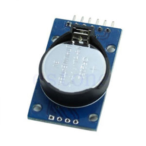
DS3231 Precise Real Time Clock Module I2C RTC AT24C32
DS3231 is a low-cost, extremely accurate I2C real-time clock (RTC), with an integrated temperature-compensated crystal oscillator (TCXO) and crystal.The device incorporates a battery input, disconnect the main power supply and maintains accurate timekeeping.Integrated oscillator improve long-term accuracy of the device and reduces the number of components of the production line.Real time clock generator seconds, minutes, hours, day, date, month and year timing and provide valid until the year 2100 leap year compensationDS3231 available in commercial and industrial temperature ranges, using a 16-pin 300mil SO package.RTC maintains seconds, minutes, hours, day, date, month, and year information. Less than 31 days of the month, the end date will be automatically adjusted, including corrections for leap year.Clock operates in either the 24 hours or band / AM / PM indication of the 12-hour format. Provides two configurable alarm clock and a calendar can be set to a square wave output.
Address and data are transferred serially through an I2C bidirectional bus.A precision temperature-compensated voltage reference and comparator circuit monitors the status of VCC to detect power failure, provide a reset output, and if necessary, automatically switch to the backup power supply.RST pin is monitored as generating μP reset manually.Save time and high precision addition, DS3231 also has some other features that extend the system host of additional features and a range of options.The device integrates a very precise digital temperature sensor, through the I2C * interface to access it (as the same time).Temperature sensor accuracy is ± 3 ° C. On-chip power supply control circuit can automatically detect and manage the main and standby power (i.e., low-voltage battery) to switch between the power supply.If the main power failure, the device can continue to provide accurate timing and temperature, performance is not affected.When the main power re-power or voltage value returns to within the allowable range, the on-chip reset function can be used to restart the system microprocessor.
SKU: CE-M060 -
Developments Boards, Modules & Sensors
ECG AD8232 heart ECG monitoring sensor module
The Ecg module AD8232 heart ECG monitoring sensor module Kit For Arduino is a cost-effective board use to measure the electrical activity of the heart. This electrical activity can be chart as an ECG or Electrocardiogram and output as an analog reading. ECGs can be extremely noisy, the AD8232 Single Lead Heart Rate Monitor acts as an op amp to help obtain a clear signal from the PR and QT Intervals easily.
SKU: CE-M087 -
Circuits Boards & PCB, Developments Boards, Modules & Sensors
Flame Sensor Or Fire Ignition Sensor Module 4 pin
 Circuits Boards & PCB, Developments Boards, Modules & Sensors
Flame Sensor Or Fire Ignition Sensor Module 4 pin
This tiny Flame sensor infrared receiver module ignition source detection module is Arduino compatible can use to detect flame or wavelength of the light source within 760nm~1100nm also useful for Lighter flame detect at the distance 80cm. Greater the flame, farther the test distance.It has the Detect angle of 60 degrees and very sensitive to flame spectrum. It produces the one channel output signal at D0 terminal for further processing like an alarm system or any switching system. The sensitivity is adjustable with the help of blue potentiometer given on the board.
SKU: CE-M001 -
Developments Boards, Modules & Sensors
FM Transmitter Module V2.0 Digital Module For Arduino
This module could modulate your voice on the FM radio wave(70-108 MHz). And anyone who has a radio device could receive it. We build everything on this module, which makes it very easy to build a tiny radio station. We also reate library for Arduino to work with this module
SKU: CE-M0108 -
Circuits Boards & PCB, Developments Boards, Modules & Sensors
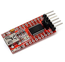
FT232RL FTDI USB to TTL Serial Adapter Module
 Circuits Boards & PCB, Developments Boards, Modules & Sensors
FT232RL FTDI USB to TTL Serial Adapter Module
Brand new Support 3.3V, 5V chipset FT232RL USB power has over current protection, using 500MA self-restore fuse RXD or TXD transceiver communication indicator Pin definition: DTR,RXD,TX,VCC,CTS,GND Pitch: 2.54mm Module size: 36mm(length)*17.5mm(width) FTDI DRIVER: Download FTDI driver to use the Module.
SKU: CE-M070