


AMS1117 is a series of low dropout three -terminal regulators with a dropout of 1.3V at 1A load current. AMS 1117 features a very low standby current 2mA compared to 5mA of competitor. Other than a fixed version, Vout = 1.2V, 1.5V, 1.8V, 2.5V, 3.3V, 5V, and 12V, AMS1117 has an adjustable version, which can provide an output voltage from 1.25 to 12V with only two external resistors. AMS 1117 offers thermal shut down and current limit functions, to assure the stability of chip and power system. And it uses trimming technique to guarantee output voltage accuracy within ±2%. Other output voltage accuracy can be customized on demand, such as ±1% AMS 1117 is available in SOT -223, TO-252 power package.
Shop
Showing 451–465 of 612 results
-
3D Printing, Motor Drives & controllers
A4988 driver 3D Printer Module Stepper Motor Driver + heat sink
 3D Printing, Motor Drives & controllers
A4988 driver 3D Printer Module Stepper Motor Driver + heat sink
The a4988 driver Stepper Motor Driver- Normal quality is a complete micro-stepping motor driver with built-in converter, easy to operate. The products can be in full, half, 1/4, 1/8 and 1/16 step mode of operation bipolar stepper motor, output drive performance up to 35 V and ± 2 A. a4988 driver Stepper Motor Driver includes a fixed off-time current regulator, the regulator can be in slow or mixed decay mode. The converter is the key to the easy implementation of the A4988. As long as the input of a pulse in the “step” in the input can be driven motor, micro-step
SKU: CE-M063 -
Modules & Sensors, Motor Drives & controllers
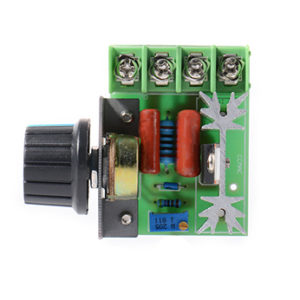
AC 220V 2000W SCR Voltage Regulator Dimming Dimmers Speed Controller Thermostat
 Modules & Sensors, Motor Drives & controllers
AC 220V 2000W SCR Voltage Regulator Dimming Dimmers Speed Controller Thermostat
Connect this device with lamp or home appliance in a series connection, then rotate the knob for dimming, speed, voltage, temperature control.As the power has very big,so the normal home appliances or small factories enough to use.This pressure regulator with two-way high power silicon controlled, potentiometer have nuts, can use not need add any components, very convenient and practical.Connect this device with lamp or home appliance in a series connection, then rotate the knob for dimming, speed, voltage, temperature control.Applicable Appliance: Electric furnace, water heater, lamps, small motor, electric iron. etc
SKU: CE-M012 -
Developments Boards, Modules & Sensors, Robots & Kits
ADXL345 3-Axis Tilt Digital Gravity Acceleration Sensor
 Developments Boards, Modules & Sensors, Robots & Kits
ADXL345 3-Axis Tilt Digital Gravity Acceleration Sensor
ADXL345 Tripple Axis Accelerometer Board is a small, thin, low power, 3-axis accelerometer with high resolution (13-bit) measurement at up to ±16g. Digital output data is format as 16-bit twos complement and is accessible through either a SPI (3- or 4-wire) or I2C digital interface. calcuttaelectronics.com
The ADXL345 Tripple Axis Accelerometer Board is well suited for mobile device applications. It measures the static acceleration of gravity in tilt-sensing applications, as well as dynamic acceleration resulting from motion or shock. Its high resolution (4 mg/LSB) enables measurement of inclination changes less than 1.0°.
Several special sensing functions are provided. Activity and inactivity sensing detect the presence or lack of motion and if the acceleration on any axis exceeds a user-set level. Tap sensing detects single and double taps. Free-fall sensing detects if the device is falling. These functions can be mapped to one of two interrupt output pins. An integrated, patent pending 32-level first in, first out (FIFO) buffer can be used to store data to minimize host processor intervention.
Low power modes enable intelligent motion-based power management with threshold sensing and active acceleration measurement at extremely low power dissipation.
SKU: CE-M062 -
-
Circuits Boards & PCB, Components
Air-core Coil Adjustable Inductance 3.5T
Low frequency inductors are constructed like transformers, with cores of electrical steel laminated to prevent eddy currents. … Some inductors have an adjustable core, which enables changing of the inductance. Inductors used to block very high frequencies are sometimes made by stringing a ferrite bead on a wire.
SKU: CE-C006 -
Developments Boards, Modules & Sensors
Alcohol Sensor MQ3 Module for all MCU
This is a simple to use MQ-3 Alcohol Detector Gas Sensor Module which can sense the presence of Alcohol in the air. The module uses our MQ-3 sensor. It simplifies the interface to the odd pin spacing of the sensor and provides an interface through standard 4 x 0.1″ header pins. It provides an analog output corresponding to the concentration of the gas in the air and an easy to use digital output. The onboard potentiometer can be used to set the maximum gas concentration beyond which the digital output gets triggered. Just power the module with 5V set the threshold and you can start getting the gas concentration of the air around the sensor! An onboard LED signals the presence of any gas. Perfect sensing alcohol concentration on your breath just likes common breathalyzer.
SKU: CE-M095 -
SMD
AMS1117-1.8V SOT-223 1.8V Fixed Linear Voltage Regulator
AMS1117 is a series of low dropout three -terminal regulators with a dropout of 1.3V at 1A load current. AMS 1117 features a very low standby current 2mA compared to 5mA of competitor. Other than a fixed version, Vout = 1.2V, 1.5V, 1.8V, 2.5V, 3.3V, 5V, and 12V, AMS1117 has an adjustable version, which can provide an output voltage from 1.25 to 12V with only two external resistors. AMS 1117 offers thermal shut down and current limit functions, to assure the stability of chip and power system. And it uses trimming technique to guarantee output voltage accuracy within ±2%. Other output voltage accuracy can be customized on demand, such as ±1% AMS 1117 is available in SOT -223, TO-252 power package.
SKU: CE-C003-1 -
SMD
AMS1117-5.0V SOT-223 5V Fixed Linear Voltage Regulator (SMD)
AMS1117 is a series of low dropout three -terminal regulators with a dropout of 1.3V at 1A load current. AMS 1117 features a very low standby current 2mA compared to 5mA of competitor. Other than a fixed version, Vout = 1.2V, 1.5V, 1.8V, 2.5V, 3.3V, 5V, and 12V, AMS1117 has an adjustable version, which can provide an output voltage from 1.25 to 12V with only two external resistors. AMS 1117 offers thermal shut down and current limit functions, to assure the stability of chip and power system. And it uses trimming technique to guarantee output voltage accuracy within ±2%. Other output voltage accuracy can be customized on demand, such as ±1% AMS 1117 is available in SOT -223, TO-252 power package.
SKU: CE-C003 -
Developments Boards, Modules & Sensors, Robots & Kits
APDS-9930 Non-contact proximity and Ambient Light sensor
 Developments Boards, Modules & Sensors, Robots & Kits
APDS-9930 Non-contact proximity and Ambient Light sensor
APDS-9930 is a digital I2C compatible interface ambient light sensor (ALS) and proximity sensor with IR LED in a single 8-pin package. The ambient light sensor utilizes dual photodiodes to approximate the human eye response with a low lux performance at 0.01 lux. This high sensitivity allows for the device to operate behind a darkened glass. The proximity sensor is fully calibrated to detection of objects to 100 mm thus eliminating the need for factory calibration of the end equipment or sub-assembly. The proximity detection feature operates well from bright sunlight to dark rooms. The addition of the micro-optics lenses within the module, provide highly efficient transmission and reception of infrared energy which lowers overall power dissipation. In addition, an internal state machine provides the ability to put the device into a low power mode in between ALS and proximity measurements providing very low average power consumption.
SKU: CE-M088 -
Developments Boards
Arduino UNO R3 Atmega16U2 With Cable
The Arduino Uno R3 is a micro-controller board base on the ATmega328. It has 14 digital input/output pins (of which 6 can be used as PWM outputs); 6 analog inputs, a 16 MHz ceramic resonator, a USB connection, a power jack, an ICSP header, and a reset button. It contains everything need to support the micro-controller; simply connect it to a computer with a USB cable or power it with a AC-to-DC adapter or battery to get start.
The Arduino Uno R3 differs from all preceding boards in that it does not use the FTDI USB-to-serial driver chip. Instead, it features the Atmega16U2 (Atmega8U2 up to version R2) program as a USB-to-serial converter. Revision 2 of the Uno board has a resistor pulling the 8U2 HWB line to ground, making it easier to put into DFU mode.
“Uno” means one in Italian and is name to mark the upcoming release of Arduino 1.0. The Uno and version 1.0 will be the reference versions of Arduino, moving forward. The Uno is the latest in a series of USB Arduino boards, and the reference model for the Arduino platform; for a comparison with previous versions, see the index of Arduino boards.
Note: The Arduino Uno R3 reference design can use an Atmega8, 168, or 328, Current models use an ATmega328, but an Atmega8 is shown in the schematic for reference. The pin configuration is identical on all three processors.
Power :
The Arduino Uno R3 can be powered via the USB connection or with an external power supply. The power source is selected automatically.
External (non-USB) power can come either from an AC-to-DC adapter (wall-wart) or battery. The adapter can be connected by plugging a 2.1mm center-positive plug into the board’s power jack. Leads from a battery can be inserted in the Gnd and Vin pin headers of the POWER connector.
The board can operate on an external supply of 6 to 20 volts. If supplied with less than 7V, however, the 5V pin may supply less than five volts and the board may be unstable. If using more than 12V, the voltage regulator may overheat and damage the board. The recommended range is 7 to 12 volts.
The power pins are as follows :
- VIN. The input voltage to the Arduino board when it’s using an external power source (as opposed to 5 volts from the USB connection or other regulated power source). You can supply voltage through this pin, or, if supplying voltage via the power jack, access it through this pin.
- 5V.This pin outputs a regulated 5V from the regulator on the board. The board can be supplied with power either from the DC power jack (7 – 12V), the USB connector (5V), or the VIN pin of the board (7-12V). Supplying voltage via the 5V or 3.3V pins bypasses the regulator, and can damage your board. We don’t advise it.
- 3V3. A 3.3 volt supply generated by the on-board regulator. Maximum current draw is 50 mA.
- GND. Ground pins.
- IOREF. This pin on the Arduino board provides the voltage reference with which the microcontroller operates. A properly configured shield can read the IOREF pin voltage and select the appropriate power source or enable voltage translators on the outputs for working with the 5V or 3.3V.
Memory :
The ATmega328 has 32 KB (with 0.5 KB used for the bootloader). It also has 2 KB of SRAM and 1 KB of EEPROM (which can be read and written with the EEPROM library).
Input and Output :
Each of the 14 digital pins on the Uno can be used as an input or output, using pinMode(), digitalWrite(), anddigitalRead() functions. They operate at 5 volts. Each pin can provide or receive a maximum of 40 mA and has an internal pull-up resistor (disconnected by default) of 20-50 kOhms. In addition, some pins have specialized functions:
- Serial: 0 (RX) and 1 (TX). Used to receive (RX) and transmit (TX) TTL serial data. These pins are connected to the corresponding pins of the ATmega8U2 USB-to-TTL Serial chip.
- External Interrupts: 2 and 3. These pins can be configured to trigger an interrupt on a low value, a rising or falling edge, or a change in value. See the attachInterrupt() function for details.
- PWM: 3, 5, 6, 9, 10, and 11. Provide 8-bit PWM output with the analogWrite() function.
- SPI: 10 (SS), 11 (MOSI), 12 (MISO), 13 (SCK). These pins support SPI communication using the SPI library.
- LED: 13. There is a built-in LED connected to digital pin 13. When the pin is HIGH value, the LED is on, when the pin is LOW, it’s off.
The Arduino Uno R3 has 6 analog inputs, labeled A0 through A5, each of which provide 10 bits of resolution (i.e. 1024 different values). By default they measure from ground to 5 volts, though is it possible to change the upper end of their range using the AREF pin and the analogReference() function. Additionally, some pins have specialized functionality:
- TWI: A4 or SDA pin and A5 or SCL pin. Support TWI communication using the Wire library.
There are a couple of other pins on the board:
- AREF. Reference voltage for the analog inputs. Used with analogReference().
- Reset. Bring this line LOW to reset the microcontroller. Typically used to add a reset button to shields which block the one on the board.
See also the mapping between Arduino pins and ATmega328 ports. The mapping for the Atmega8, 168, and 328 is identical.
Communication :
The Arduino Uno R3 has a number of facilities for communicating with a computer, another Arduino, or other microcontrollers. The ATmega328 provides UART TTL (5V) serial communication, which is available on digital pins 0 (RX) and 1 (TX). An ATmega16U2 on the board channels this serial communication over USB and appears as a virtual com port to software on the computer. The ’16U2 firmware uses the standard USB COM drivers, and no external driver is needed. However, on Windows, a .inf file is required. The Arduino software includes a serial monitor which allows simple textual data to be sent to and from the Arduino board. The RX and TX LEDs on the board will flash when data is being transmitted via the USB-to-serial chip and USB connection to the computer (but not for serial communication on pins 0 and 1).
A SoftwareSerial library allows for serial communication on any of the Uno’s digital pins.
The ATmega328 also supports I2C (TWI) and SPI communication. The Arduino Uno R3 software includes a Wire library to simplify use of the I2C bus; see the documentation for details. For SPI communication, use the SPI library.
Programming :
The Arduino Uno R3 can be program with the Arduino software (download). Select “Arduino Uno from the Tools > Board menu (according to the micro-controller on your board). For details, see the reference and tutorials.
The ATmega328 on the Arduino Uno R3 comes pre burn with a bootloader that allows you to upload new code to it without the use of an external hardware programmer. It communicates using the original STK500 protocol (reference, C header files).
You can also bypass the bootloader and program the microcontroller through the ICSP (In-Circuit Serial Programming) header; see these instructions for details.
The ATmega16U2 (or 8U2 in the rev1 and rev2 boards) firmware source code is available . The ATmega16U2/8U2 is load with a DFU bootloader, which can be activate by:
- On Rev1 boards: connecting the solder jumper on the back of the board (near the map of Italy) and then resetting the 8U2.
- On Rev2 or later boards: there is a resistor that pulling the 8U2/16U2 HWB line to ground, making it easier to put into DFU mode.
You can then use Atmel’s FLIP software (Windows) or the DFU programmer (Mac OS X and Linux) to load a new firmware. Or you can use the ISP header with an external programmer (overwriting the DFU bootloader). See this user-contributed tutorial for more information.
Automatic (Software) Reset :
Rather than requiring a physical press of the reset button before an upload, the Arduino Uno is design in a way that allows it to be reset by software running on a connect computer. One of the hardware flow control lines (DTR) of theATmega8U2/16U2 is connected to the reset line of the ATmega328 via a 100 nano-farad capacitor. When this line is assert (taken low), the reset line drops long enough to reset the chip. The Arduino software uses this capability to allow you to upload code by simply pressing the upload button in the Arduino environment. This means that the boot-loader can have a shorter timeout, as the lowering of DTR can be well-coordinate with the start of the upload.
This setup has other implications. When the Uno is connect to either a computer running Mac OS X or Linux, it resets each time a connection is made to it from software (via USB). For the following half-second or so, the boot-loader is running on the Uno. While it is program to ignore malformed data (i.e. anything besides an upload of new code), it will intercept the first few bytes of data sent to the board after a connection is open. If a sketch running on the board receives one-time configuration or other data when it first starts, make sure that the software with which it communicates waits a second after opening the connection and before sending this data.
The Arduino Uno R3 contains a trace that can be cut to disable the auto-reset. The pads on either side of the trace can be soldere together to re-enable it. It’s label “RESET-EN”. You may also be able to disable the auto-reset by connecting a 110 ohm resistor from 5V to the reset line; see this forum thread for details.
USB Overcurrent Protection :
The Arduino Uno has a resettable polyfuse that protects your computer’s USB ports from shorts and overcurrent. Although most computers provide their own internal protection, the fuse provides an extra layer of protection. If more than 500 mA is apply to the USB port, the fuse will automatically break the connection until the short or overload is remove.
Physical Characteristics :
The maximum length and width of the Uno PCB are 2.7 and 2.1 inches respectively, with the USB connector and power jack extending beyond the former dimension. Four screw holes allow the board to be attache to a surface or case. Note that the distance between digital pins 7 and 8 is 160 mil (0.16″), not an even multiple of the 100 mil spacing of the other pins.
Package Includes :
1 x Arduino Uno R3.
1 x USB Cable.
Specifications and Features :
- Micro-controller : ATmega328
- Operating Voltage : 5V
- Input Voltage (recommended) : 7-12V
- Input Voltage (limits) : 6-20V
- Digital I/O Pins : 14 (of which 6 provide PWM output)
- Analog Input Pins : 6
- DC Current per I/O Pin : 40 mA
- DC Current for 3.3V Pin : 50 mA
- Flash Memory : 32 KB (ATmega328) of which 0.5 KB used by bootloader
- SRAM : 2 KB (ATmega328)
- EEPROM: 1 KB (ATmega328)
- Clock Speed: 16 MHz.
- 1.0 pinout : added SDA and SCL pins that are near to the AREF pin and two other new pins place near to the RESET pin, the IOREF that allow the shields to adapt to the voltage provide from the board. In future, shields will be compatible with both the board that uses the AVR, which operates with 5V and with the Arduino Due that operates with 3.3V. The second one is a not connect pin, that is reserve for future purposes.
- Stronger RESET circuit.
- Atmega 16U2 replace the 8U2.
SKU: CE-A005 -
Developments Boards
Arduino Pro Mini ATMEGA328P 3.3V/8MHz
The Pro Mini is a microcontroller board based on the ATmega328 for Arduino. With 14 digital input / output pins (of which 6 can be used as PWM outputs), 8 analog inputs, an on-board resonator, a reset button, and holes for mounting pin headers. Six pin header can be connected to an FTDI cable to provide USB power and communication to the board.
SKU: CE-A001 -
Components, Developments Boards, integrated circuit
ATMEGA328-PU with arduino Bootloader 2018 version
 Components, Developments Boards, integrated circuit
ATMEGA328-PU with arduino Bootloader 2018 version
Microchip Technology ATmega328 8-bit AVR® Microcontrollers (MCUs) are high-performance RISC-based devices that combine 32KB ISP Flash memory with read-while-write capabilities, 1KB EEPROM, 2KB SRAM, 23 general-purpose I/O lines, 32 general-purpose working registers, serial programmable USART, and more.ATmega328 MCUs execute powerful instructions in a single clock cycle, allowing the device to achieve throughputs approaching 1 MIPS per MHz while balancing power consumption and processing speed. These Microchip MCUs are designed for use in industrial automation and home and building automation.
SKU: IC001


